- sales@fokca.com info@fokca.com
- WhatsApp: +86 150 5749 1870

Custom Cylinders & System Solutions Manufacturer | Est. 1998
Custom Cylinders & System Solutions Manufacturer | Est. 1998

Feb 06, 2026

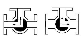
In many industrial sites, a pneumatic ball valve is regarded as a reliable shut-off component, yet engineers sometimes encounter an unusual situation: even when the valve is fully closed, abnormal pressure may still build up inside the valve cavity. This is not necessarily a quality defect, but a result of the structural characteristics of ball valves and specific working conditions. Understanding how the cavity becomes sealed by upstream and downstream media is the starting point for risk analysis.
A ball valve is a quarter turn pneumatic ball valve. When the ball rotates to the closed position, both seats form sealing on the upstream and downstream sides. If pressure exists on both ends, the cavity turns into a small isolated chamber. This is common in pneumatic stainless steel ball valve used for chemical processes. Many users selecting a high pressure pneumatic ball valve focus only on pipeline pressure and overlook the independent pressure environment inside the valve.
Under stable temperature, the cavity pressure remains close to the medium state at the moment of closure. However, real plants experience frequent thermal variation, and the trapped medium cannot escape freely, leading to pressure deviation.
Whether it is a pneumatic ball valve for steam or a pneumatic ball valve for gas, the medium expands with temperature. When the valve is installed outdoors or near heat sources, the increased volume has no outlet, and pressure is transferred to the seats and ball surface. For a single acting pneumatic ball valve, the additional internal pressure may even influence the required operating torque.
Liquids present higher risk. Because of very low compressibility, a small expansion can generate significant pressure, which explains why the pneumatic ball valve torque requirement sometimes rises unexpectedly.
Not all valves respond equally. Models with cavity relief holes or floating seats can mitigate the problem, while compact pneumatic ball valve with smaller internal volume is more sensitive. The following table summarizes typical scenarios:
| Working Condition | Medium Type | Risk of Cavity Pressure | Recommended Solution |
|---|---|---|---|
| Outdoor temperature rise | Liquid | High | Cavity relief design |
| Steam heating line | Vapor | Medium | Heat insulation |
| Gas pipeline | Gas | Low | Standard structure |
| Chemical process | Mixed media | High | Venting seat |
In a pneumatic ball valve automation system, the actuator does not sense real cavity pressure. When pressure becomes excessive, a double acting pneumatic ball valve may require greater force and show slow response. For an adjustable pneumatic ball valve with actuator, the abnormal pressure can distort flow characteristics and affect control accuracy.

Therefore, many pneumatic ball valve installation guide documents recommend providing a relief path or selecting valves with self-relieving seats.
The pneumatic ball valve selection guide should evaluate structure, medium and temperature together. Applications such as pneumatic ball valve for oil & gas differ greatly from pneumatic ball valve for HVAC. For cryogenic service, a low temperature pneumatic ball valve is necessary, while in high-pressure environments, stainless steel pneumatic ball valve 316 offers better safety margin.
Experience proves that choosing an improper structure is more dangerous than insufficient actuator power. Only by understanding the mechanism of cavity isolation can engineers ensure long-term reliability of pneumatic ball valves.
(FK9025)
You May Interest In

Jan 08, 2026 Blog
Why Globe Valves Cannot Fully Replace Ball Valves


Get a free sample

FOKCA ©1998-2025 All Rights Reserved Sitemap